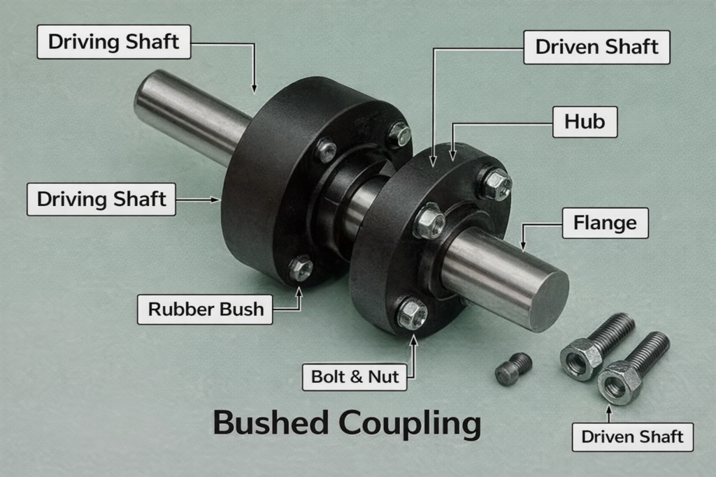
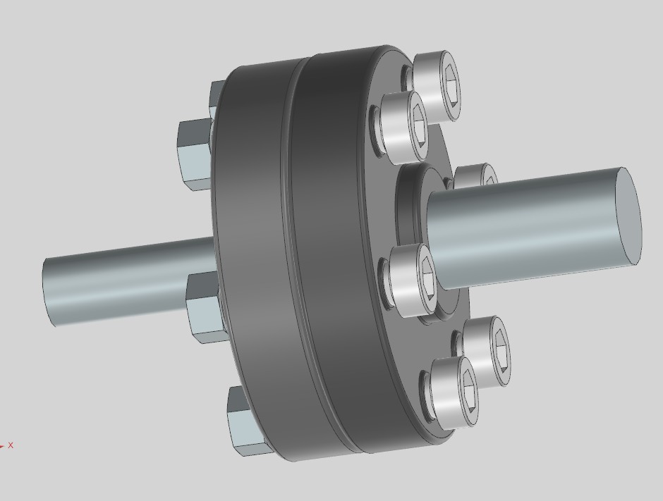
The attached image shows a 3D model of a bush coupling (also called a bushing or resilient pin-and-bush coupling), consisting of two flanges connected by a central shaft with elastomeric bushings that allow limited articulation and absorb shocks. This design is commonly used in truck-trailer fifth wheel systems, pintle hooks, or drawbar couplings to handle misalignment, vibration, and heavy towing loads..
Key Components and Function
The coupling features outer steel flanges bolted together (using hex or Allen bolts), an inner shaft/pin, and rubber or polyurethane (PU) bushings that provide damping and flexibility. It enables rotational movement (up to 15-20 degrees) and shock absorption during towing, preventing metal-to-metal contact and reducing wear on the tractor-trailer connection.
Materials Used
- Flanges and shaft: High-strength alloy steel or HSLA (High-Strength Low-Alloy) steel for durability and load capacity (typically 20T-36T ratings).
- Bushings: Polyurethane (PU) for high wear resistance and longevity, or rubber for cost-effective damping; grease fittings extend service life.
- Optional coatings: Zinc plating or powder coating for corrosion protection in harsh environments.
Applications in Trucks and Trailers
- Fifth wheel couplings: Connect tractor to semi-trailer, as in Rockinger or Jost systems for GCW up to 90T.
- Pintle hook or drawbar hitches: For rigid trailers, providing articulation.
- Landing gear and suspension linkages: Absorb shocks and allow pivoting.
Advantages
- Shock and vibration isolation extends component life and improves ride quality.
- Accommodates misalignment during turns and uneven terrain.
- Low maintenance with easy bushing replacement.
- Meets standards like AIS 091, IS 10766 for safety in Indian and global markets.
Bush couplings are vital for safe, reliable truck-trailer operation, balancing rigidity with flexibility in heavy-duty towing scenarios.
BUSHED COUPLING – DESIGN CALCULATIONS (MATH)
1️⃣ Design Torque
From transmitted power:T=N9550P
Where:
- T = Torque (N·m)
- P = Power (kW)
- N = Speed (rpm)
Design torque (with service factor K):Td=K×T
Typical K=1.3 to 1.5
2️⃣ Shaft Diameter (Torsion)
Td=16πτd3 d=(πτ16Td)1/3
Where:
- d = shaft diameter (mm)
- τ = allowable shear stress
- EN8 steel ≈ 40 MPa
3️⃣ Hub Design
Hub Outer Diameter
Dh=2d
Hub Length
L=1.5d
(Standard proportions)
4️⃣ Key Design
Key Width & Height (ISO)
b=4d,h=6d
Check for Shear:
τk=dbL2Td
Check for Crushing:
σc=dhL4Td
Allowable values:
- Shear ≈ 40 MPa
- Crushing ≈ 80 MPa
5️⃣ Flange Design
Flange Thickness
tf=0.5d
Pitch Circle Diameter (PCD)
Dp=3d
Flange Outside Diameter
Df=4d
6️⃣ Bolts & Bushes (Critical Section)
Torque Transmitted by Bushes:
Td=n×F×2Dp
Where:
- n = number of bolts
- F = force on one bush
F=nDp2Td
7️⃣ Rubber / PU Bush Stress
Compressive Stress:
σb=AF
Where:A=db×lb
Typical allowable:
- Rubber ≈ 0.5–1 MPa
- Polyurethane ≈ 1–3 MPa
8️⃣ Bolt Design (Shear Check)
τb=AbF Ab=4πdb2
Allowable shear stress:
- Bolt Grade 8.8 ≈ 80 MPa
9️⃣ Flange Bearing Pressure Check
p=tf×dbF
Must be within material bearing limits.
🔍 Example (Typical Values)
Assume:
- P=5kW
- N=1000rpm
- K=1.5
T=10009550×5=47.75N\cdotpm Td=71.6N\cdotpm d≈25mm